Monday, September 19, 2022

Signal Stat Turn Signal Switch Wiring Diagram

Signal Stat Turn Signal Switch Wiring Diagram

Rj11 Socket Wiring Diagram Australia, How to punch down an RJ11 Telephone Jack, 6.36 MB, 04:38, 387,634, CableSupply.com, 2009-08-05T00:16:07.000000Z, 19, Rj11 Socket Wiring Diagram Australia | Computacion, Redes de computadoras, Computadoras, www.pinterest.com.mx, 728 x 783, jpeg, rj11 wiring rj45 diagram cable ethernet usb jack pinout adapter cat5 female male convert using rs485 cat wires code socket, 20, rj11-socket-wiring-diagram-australia, Anime Arts

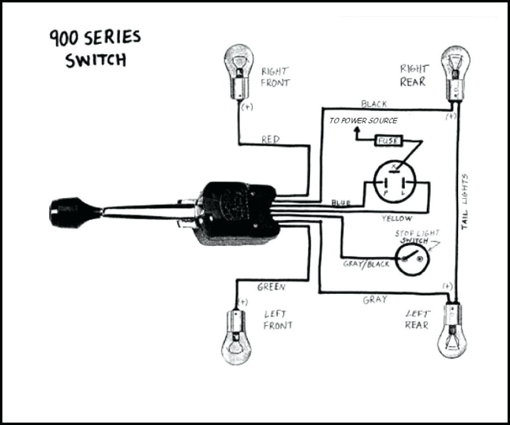
Durable die cast construction. Die cast handle with heavy duty flare tab. Heavy gauge mounting strap and hardware. Long lasting contacts extend switch life.

Each part ought to be placed and connected with different parts in specific manner. For instance , when a module will be powered up and it sends out a signal of fifty percent the voltage in addition to the technician will not know this, he'd think he provides an issue, as he would expect a new 12v. Here is a picture gallery about signal stat wiring diagram complete with the description of the image. Ch341a ch341 programmer coreboot. Signal stat 900 sigflare wiring diagramweb. net. Signal wiring stat turn switch wire ford signals 48f1 universal qqc dot consideration exactly never iptc exif delay sec. Signal stat 900 turn signal switch wiring diagram. Signal stat 900 wire wiring diagram universal ynz turn. Kit signal turn legal street relay simple.

Signal Stat 900 Wiring Diagram | Cadician's Blog

Signal Stat 900 Wiring Diagram | Cadician's Blog
Image by 2020cadillac.com

Signal Stat 900 Turn Signal Wiring Diagram - Collection - Wiring Diagram Sample

Signal Stat 900 Turn Signal Wiring Diagram - Collection - Wiring Diagram Sample
Image by faceitsalon.com

Signal Stat Turn Signal Switch Wiring Diagram - Complete Wiring Schemas

Signal Stat Turn Signal Switch Wiring Diagram - Complete Wiring Schemas
Image by wiring89.blogspot.com

Technical Signal Stat 900 11 Wire Turnsignal Switch The H A M B - Signal Stat 900 Wiring Diagram
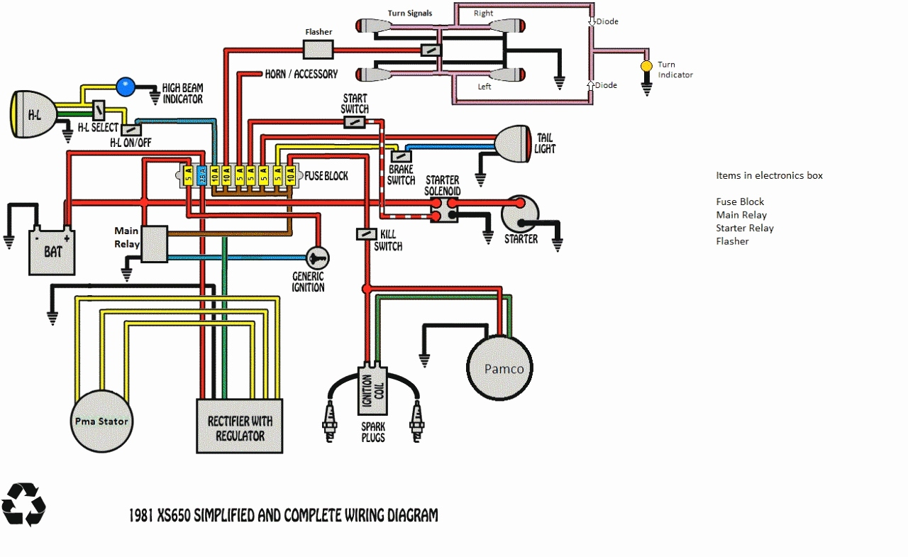
Technical Signal Stat 900 11 Wire Turnsignal Switch The H A M B - Signal Stat 900 Wiring Diagram
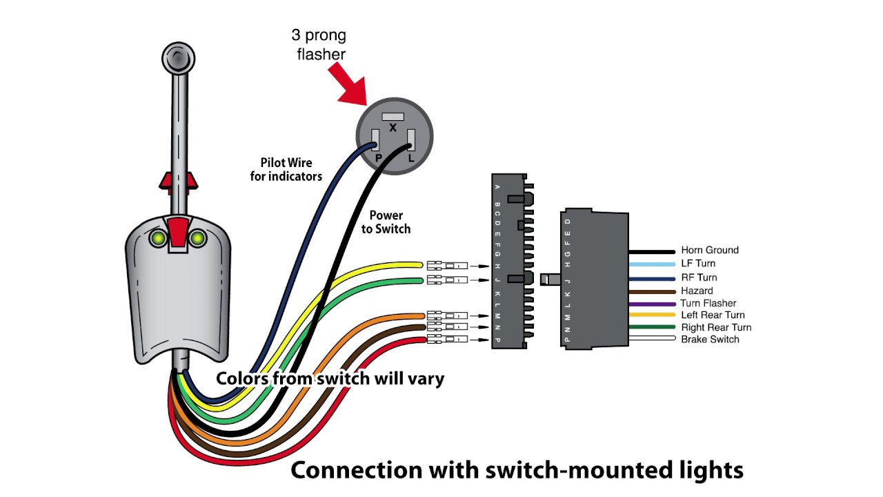
Image by annawiringdiagram.com

Signal Stat 900 Turn Signal Switch Wiring Diagram

Signal Stat 900 Turn Signal Switch Wiring Diagram
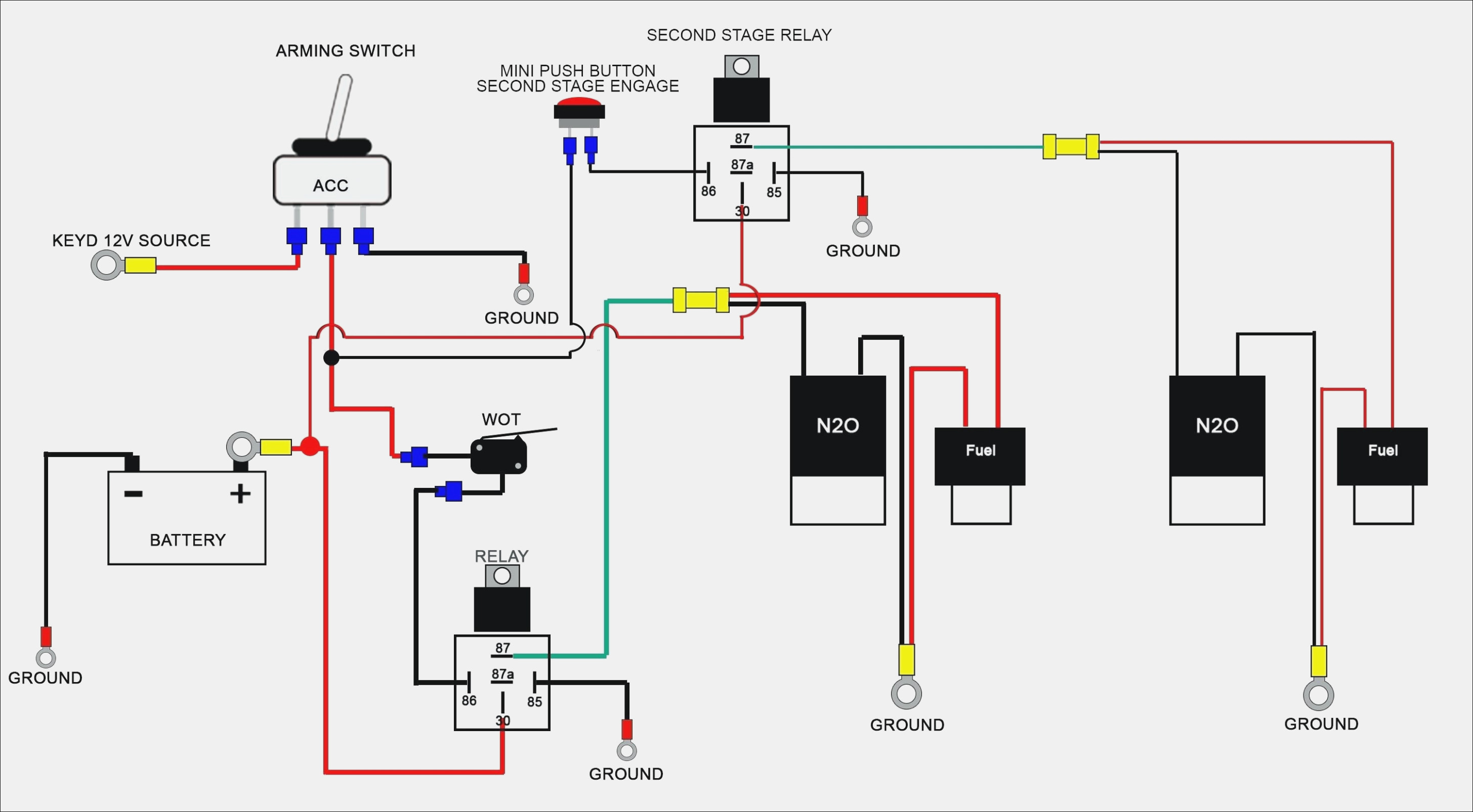
Image by diagramweb.net

Signal Stat 900 Turn Signal Switch Wiring Diagram

Signal Stat 900 Turn Signal Switch Wiring Diagram
Image by diagramweb.net

Signal Stat 900 Turn Signal Switch Wiring Diagram
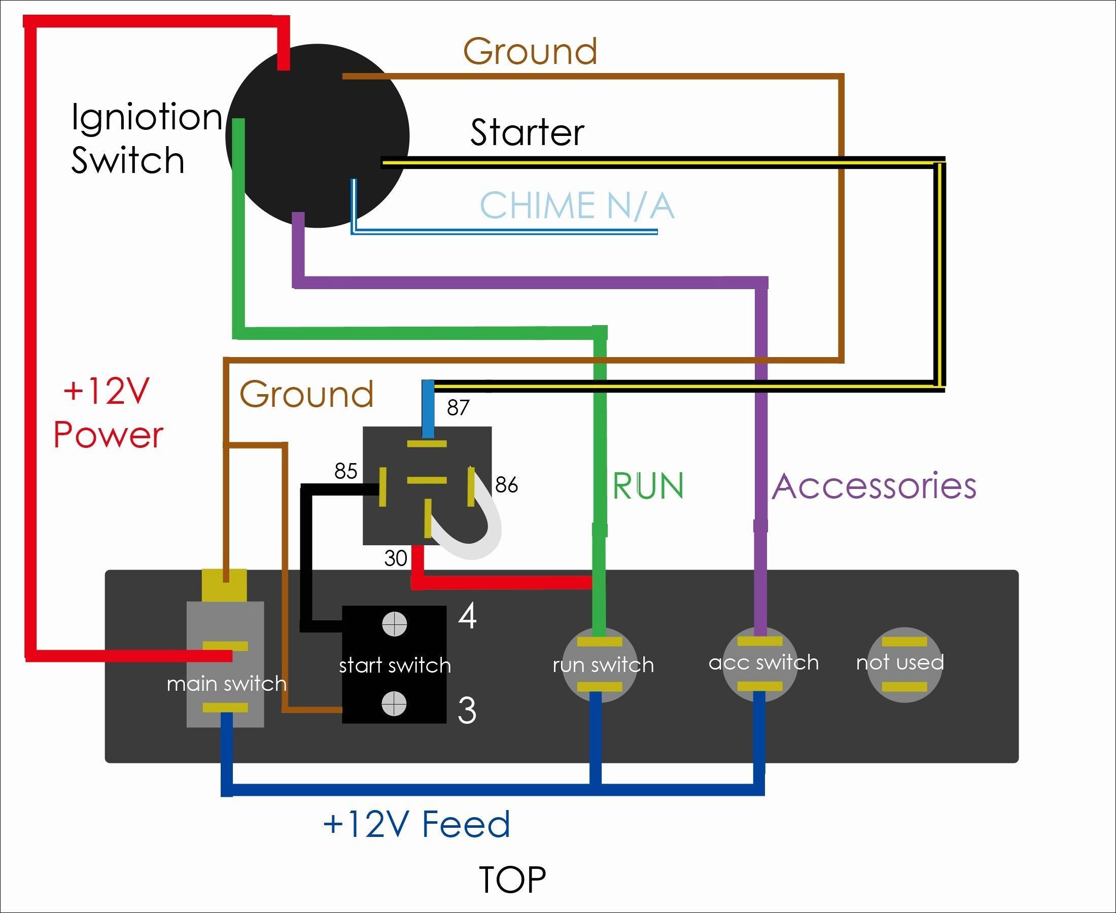
Signal Stat 900 Turn Signal Switch Wiring Diagram
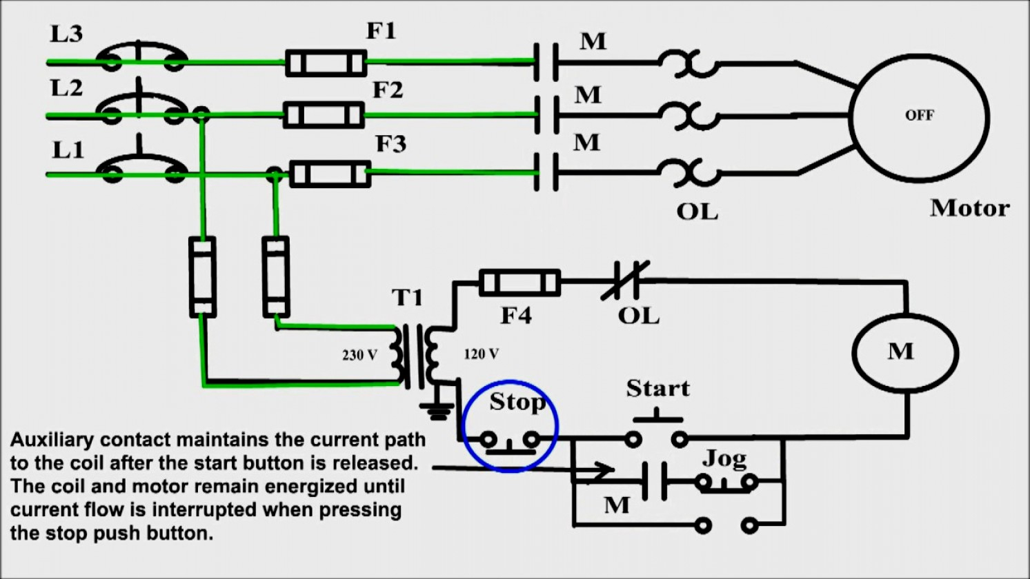
Image by diagramweb.net

Technical - Signal Stat 800 wired like a signal Stat 400? | The H.A.M.B.

Technical - Signal Stat 800 wired like a signal Stat 400? | The H.A.M.B.
Image by www.jalopyjournal.com

Technical Signal Stat 900 11 Wire Turnsignal Switch The H A M B - Signal Stat 900 Wiring Diagram

Technical Signal Stat 900 11 Wire Turnsignal Switch The H A M B - Signal Stat 900 Wiring Diagram
Image by 2020cadillac.com

Signal Stat 900 Turn Signal Switch Wiring Diagram
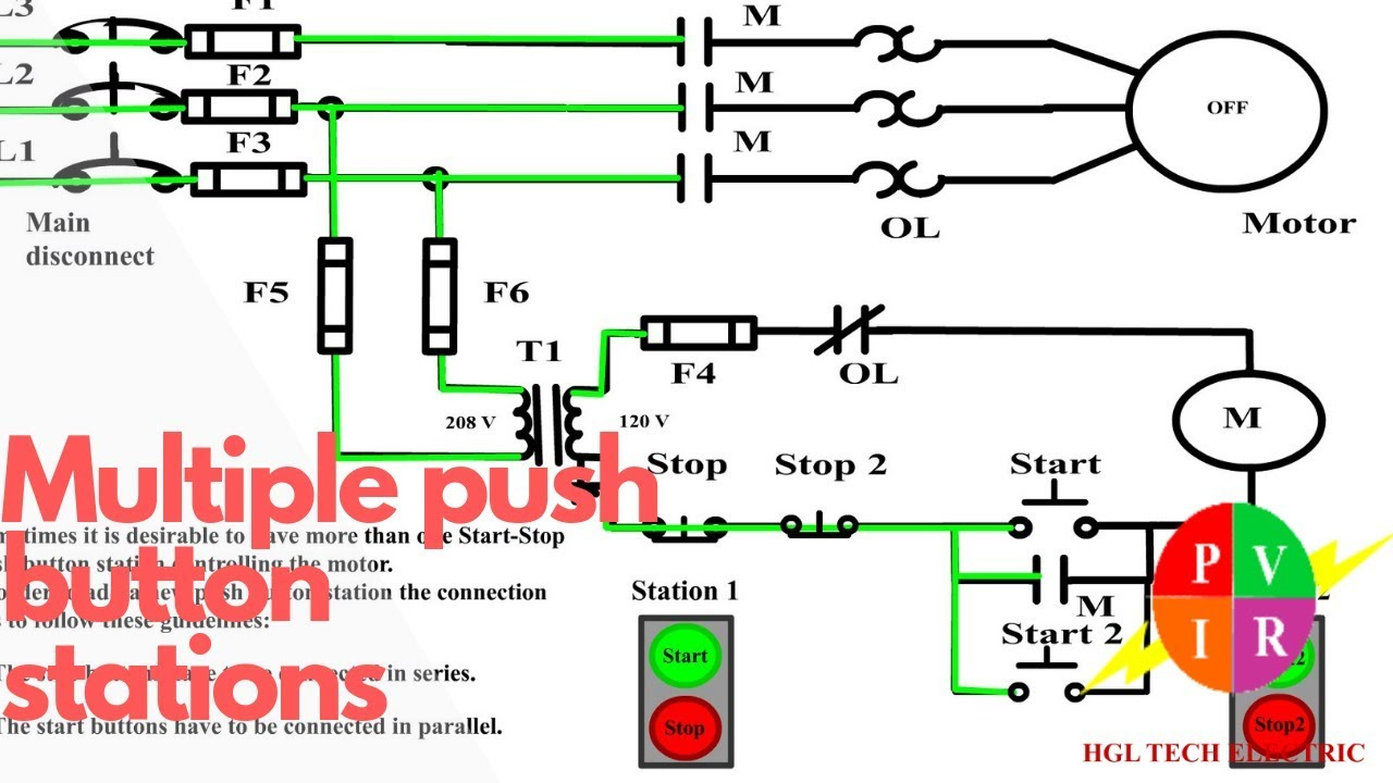
Signal Stat 900 Turn Signal Switch Wiring Diagram
Image by diagramweb.net

Start Stop Switch Wiring Diagram

Start Stop Switch Wiring Diagram

nest Hello Wiring Diagram, Nest Hello Advanced Wiring Diagram, 6.25 MB, 04:33, 63,749, gt8monster, 2018-06-16T10:14:46.000000Z, 19, Nest Hello Doorbell: 18 Questions/Answers You Need To Know - Smart Home Point, www.smarthomepoint.com, 1057 x 852, png, nest diagram hello doorbell wiring google camera chimes chime install multiple lh4 googleusercontent answers questions know need pre, 20, %ef%bb%bfnest-hello-wiring-diagram, Anime Arts

The most common use of 3 wire control is a start/stop control. See image below for an example of 3 wire control being used to pull in a contactor to start a 3 phase motor. When you press the start button and the stop button is not pressed, the 24vdc relay energizes and it pulls in the r1 contactor that feeds three phase power to the motor. Start stop wiring diagram one switch.

As stated earlier, the lines at a push button starter switch wiring diagram represents wires. I am here with giving you a vfd start stop wiring diagram for running a vfd through panel board push button and keypad of the vfd (it is called hmi). Start stop switch wiring diagram from cdn11. bigcommerce. com to properly read a wiring diagram, one has to find out how the components in the system operate. For example , when a module is powered up and it also sends out a new signal of 50 percent the voltage in addition to the technician would not know this, he'd think he offers an issue, as this individual would. Discuss wiring diagram for start/stop ? In the electrical forum area at electriciansforums. net. Feb 11, 2012 #1. Your diagram shows a 3 pole contactor using 1 pair of contacts as slave. Ifr you want to switch 3 phase, you would need 3 main contacts ans a fourth one as slave, reply to telectrix.

Start Stop Push Button Wiring Diagram | Wiring Diagram

Start Stop Push Button Wiring Diagram | Wiring Diagram
Image by annawiringdiagram.com

Dont Know How To Wire A Start/stop Switch To Motor - Electrical - DIY Chatroom Home Improvement

Dont Know How To Wire A Start/stop Switch To Motor - Electrical - DIY Chatroom Home Improvement
Image by www.diychatroom.com

Collection Of Start Stop Push button Station Wiring Diagram Download

Collection Of Start Stop Push button Station Wiring Diagram Download
Image by worldvisionsummerfest.com

Start Stop Push Button Wiring Diagram for Android - APK Download

Start Stop Push Button Wiring Diagram for Android - APK Download
Image by apkpure.com

Start Stop Push Button Wiring Diagram | Wiring Diagram

Start Stop Push Button Wiring Diagram | Wiring Diagram
Image by annawiringdiagram.com

Start Stop Push Button Wiring Diagram - Drivenheisenberg

Start Stop Push Button Wiring Diagram - Drivenheisenberg
Image by drivenheisenberg.blogspot.com

Start Stop Push Button Wiring Diagram | Wiring Diagram

Start Stop Push Button Wiring Diagram | Wiring Diagram
Image by annawiringdiagram.com

3 Wire Start Stop Wiring-Diagram | Elec Eng World | Wire, Diagram, Circuit

3 Wire Start Stop Wiring-Diagram | Elec Eng World | Wire, Diagram, Circuit
Image by www.pinterest.com

Two Wire & Three Wire Motor Control Circuit | Motor Control Circuit Diagram | Electrical A2Z

Two Wire & Three Wire Motor Control Circuit | Motor Control Circuit Diagram | Electrical A2Z
Image by electricala2z.com

Start Stop Wiring Diagram | Free Wiring Diagram

Start Stop Wiring Diagram | Free Wiring Diagram
Image by ricardolevinsmorales.com

Sunday, September 18, 2022

Wiring Diagram Hyundai Santa Fe 2004

Wiring Diagram Hyundai Santa Fe 2004

Rj11 Socket Wiring Diagram Australia, How to punch down an RJ11 Telephone Jack, 6.36 MB, 04:38, 387,634, CableSupply.com, 2009-08-05T00:16:07.000000Z, 19, Rj11 Socket Wiring Diagram Australia | Computacion, Redes de computadoras, Computadoras, www.pinterest.com.mx, 728 x 783, jpeg, rj11 wiring rj45 diagram cable ethernet usb jack pinout adapter cat5 female male convert using rs485 cat wires code socket, 20, rj11-socket-wiring-diagram-australia, Anime Arts

Automotive electricians portal llc address: 8 the green, ste a, dover, de 19901 Belt honda odyssey diagram serpentine 2007 fe santa hyundai timing diagrams 1995 routing replacement liter fixya 2carpros. Fuse box diagram hyundai santa fe (cm;

Hyundai santa fe 2004 wiring throttle position sensor collection faceitsalon. com. Genuine hyundai parts, the right choice. Hyundaipartsdeal. com offers the wholesale prices for genuine 2004 hyundai santa fe parts. Parts like engine wiring are shipped directly from authorized hyundai dealers and backed by the. Rear hyundai 2003 elantra brake line diagram fe santa replacement brakes. Elantra fuse getz electrique sonata lancer veloster altima easywiring autoradio. Hyundai santa fe 2004 wiring throttle position sensor collection. 2004 hyundai santa fe wiring diagram. Free wiring diagrams with regard to 2004 hyundai santa fe wiring diagram by admin from the thousand photographs on the internet with regards to 2004 hyundai santa fe wiring diagram, picks the best selections with greatest resolution just for you, and now this images is usually one among graphics libraries in.

[Wiring Diagram] 2004 Hyundai Santa Fe Security

[Wiring Diagram] 2004 Hyundai Santa Fe Security
Image by schemacache.com

2004 Hyundai Santa Fe Radio Wiring Diagram - Wiring Diagram and Schematic

2004 Hyundai Santa Fe Radio Wiring Diagram - Wiring Diagram and Schematic
Image by wiring.hpricorpcom.com

2004 Hyundai Santa Fe Monsoon Wiring Diagram Images | Wiring Collection

2004 Hyundai Santa Fe Monsoon Wiring Diagram Images | Wiring Collection
Image by headcontrolsystem.com

2004 Hyundai Santa Fe Monsoon Wiring Diagram

2004 Hyundai Santa Fe Monsoon Wiring Diagram
Image by wiringall.com

2004 Hyundai Santa Fe Radio Wiring Diagram - Database - Wiring Diagram Sample

2004 Hyundai Santa Fe Radio Wiring Diagram - Database - Wiring Diagram Sample
Image by faceitsalon.com

2004 Hyundai Santa Fe Monsoon Wiring Diagram

2004 Hyundai Santa Fe Monsoon Wiring Diagram
Image by wiringall.com

2004 Hyundai Santa Fe Wiring Diagram Collection - Wiring Diagram Sample

2004 Hyundai Santa Fe Wiring Diagram Collection - Wiring Diagram Sample
Image by faceitsalon.com

2004 Hyundai Santa Fe Wiring Schematic - Wiring Diagram

2004 Hyundai Santa Fe Wiring Schematic - Wiring Diagram
Image by wiringdiagram.2bitboer.com

2004 Santa Fe Monsoon Wiring Diagram

2004 Santa Fe Monsoon Wiring Diagram
Image by wiringall.com

Wiring Diagram Hyundai Santum Fe 2004 : 2004 Hyundai Santa Fe Radio Wiring - Wiring Forums

Wiring Diagram Hyundai Santum Fe 2004 : 2004 Hyundai Santa Fe Radio Wiring - Wiring Forums
Image by diyonline26.blogspot.com

Saturday, September 17, 2022

Glowshift Gauge Wiring Diagram

Glowshift Gauge Wiring Diagram

nest Hello Wiring Diagram, Nest Hello Advanced Wiring Diagram, 6.25 MB, 04:33, 63,749, gt8monster, 2018-06-16T10:14:46.000000Z, 19, Nest Hello Doorbell: 18 Questions/Answers You Need To Know - Smart Home Point, www.smarthomepoint.com, 1057 x 852, png, nest diagram hello doorbell wiring google camera chimes chime install multiple lh4 googleusercontent answers questions know need pre, 20, %ef%bb%bfnest-hello-wiring-diagram, Anime Arts

Connect the orange wire of the gauge to the positive Wiring harnes cummin exhaust temperature. Probe replacement exhaust temperature electronic wiring egt. Using automotive grade wiring (18 gauge);

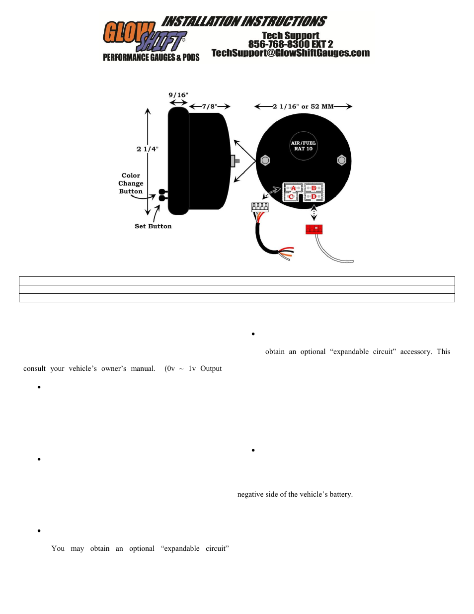
It may be connected to the fuse panel, an accessory wire, or any positive 12 volt source that turns on and off with the ignition. Using automotive grade wiring (18 gauge); Connect the black wire to any good (unpainted) ground. Glowshift gauges is world renowned for providing exceptionally crafted and competitively priced automotive gauges with an extensive variety of styles and options. Over the years, glowshift's lineup of performance gauges and gauge pods has grown exponentially to include many of the most sought after gauges in the. 12 gauge wire mm simple glowshift gauges wiring diagram our battery cable is american made and comes in gauge awg sizes of 6 4 2 1 10 20 30 and 40 with 6 gauge being the smallest and 40 gauge being the largest. Discussion starter · #1 · aug 17, 2009. Glowshift's 7 color series 3 gauge wiring kit is a complete wiring harness that allows you to easily wire 3 tinted 7, black 7 or white 7 color gauges from one harness. This wiring kit features both sensor and power wires combined for each gauge.

Glowshift Trans Temp Gauge Wiring Diagram

Glowshift Trans Temp Gauge Wiring Diagram
Image by diagramweb.net

Glowshift Trans Temp Gauge Wiring Diagram

Glowshift Trans Temp Gauge Wiring Diagram
Image by diagramweb.net

Glowshift Gauges Wiring Diagram - 36

Glowshift Gauges Wiring Diagram - 36
Image by shs99reunion.blogspot.com

Glowshift Egt Gauge Wiring Diagram - Wiring Diagram

Glowshift Egt Gauge Wiring Diagram - Wiring Diagram
Image by wiringdiagram.2bitboer.com

Wrx Glowshift Wiring Diagram : Boost Water Temp Gauge Install Picture Heavy Club Liberty Asn Au

Wrx Glowshift Wiring Diagram : Boost Water Temp Gauge Install Picture Heavy Club Liberty Asn Au
Image by 9007-wiring-diagram71.blogspot.com

Glowshift Gauges Wiring Diagram - 36

Glowshift Gauges Wiring Diagram - 36
Image by shs99reunion.blogspot.com

60 Wiring Diagram 2003 Colant Temperature Sensor Powerstroke - Wiring Diagram Networks

60 Wiring Diagram 2003 Colant Temperature Sensor Powerstroke - Wiring Diagram Networks
Image by kelvin-okl.blogspot.com

GlowShift MaxTow Series Water Temperature Gauge User Manual | 3 pages | Also for: Water

GlowShift MaxTow Series Water Temperature Gauge User Manual | 3 pages | Also for: Water
Image by www.manualsdir.com

Glowshift Boost Gauge Wiring Diagram

Glowshift Boost Gauge Wiring Diagram
Image by schematron.org

Glowshift Oil Pressure Gauge Wiring

Glowshift Oil Pressure Gauge Wiring
Image by schematron.org

Friday, September 16, 2022

Single Phase Contactor Wiring Diagram

Single Phase Contactor Wiring Diagram

nest Hello Wiring Diagram, Nest Hello Advanced Wiring Diagram, 6.25 MB, 04:33, 63,749, gt8monster, 2018-06-16T10:14:46.000000Z, 19, Nest Hello Doorbell: 18 Questions/Answers You Need To Know - Smart Home Point, www.smarthomepoint.com, 1057 x 852, png, nest diagram hello doorbell wiring google camera chimes chime install multiple lh4 googleusercontent answers questions know need pre, 20, %ef%bb%bfnest-hello-wiring-diagram, Anime Arts

A single phase motor is an electrically powered rotary machine that can turn electric energy into mechanical energy. It works by using a single phase power s. If you are looking for how to run 3 phase motor with 1 phase power supply | earth bondhon you've visit to the right web. We have 9 pics about how to run 3 phase motor with 1 phase power supply | earth bondhon like wiring diagram , single phase motor contactor off , on switches control, wiring 2 phase ( 380volt) motor to 1 phase (220 volt) power with and also.

3 phase reversing motor wiring diagram single pole double throw a using hestiahelper. blogspot. com. Wiring spdt reversing schematron. Trying to wire a 220v single phase with a mag contactor and a momentary www. justanswer. com. Contactor wire 220v mag phase trying single. 3 phase contactor wiring diagram for your needs. Single phase motor to a reversing contactor all about circuits 3 forward reverse switch wiring diagram earth bondhon automatic dust collection for small s instructions gg500c with thermal protection 220vac coil how use vfd ato com interlocking methods control basic aim manual page 57 motors and controls maintenance north america water franklin. How to wire schneider lc1d contactor. 16 pictures about how to wire schneider lc1d contactor : Schneider contactor wiring diagram pdf | electrical wiring, [dy_5245] ask the trades wiring a dol starter download diagram and also [dy_5245] ask the trades wiring a.

Single Phase Motor Contactor Wiring Diagram | Elec Eng World | Electricity, Electrical

Single Phase Motor Contactor Wiring Diagram | Elec Eng World | Electricity, Electrical
Image by www.pinterest.com

single phase motor connection with magnetic contactor wiring diagram - YouTube

single phase motor connection with magnetic contactor wiring diagram - YouTube
Image by www.youtube.com

Single Phase Contactor Wiring Diagram A1 A2

Single Phase Contactor Wiring Diagram A1 A2
Image by diagramofwiring.blogspot.com

Single Phase Motor Wiring With Contactor Diagram | Electrical Online 4u

Single Phase Motor Wiring With Contactor Diagram | Electrical Online 4u
Image by www.electricalonline4u.com

Start Stop Single Phase Contactor Wiring Diagram

Start Stop Single Phase Contactor Wiring Diagram
Image by diagramofwiring.blogspot.com

Single Phase Contactor Wiring Diagram A1 A2

Single Phase Contactor Wiring Diagram A1 A2
Image by diagramofwiring.blogspot.com

Schneider Ict Contactor Wiring Diagram - Wiring Diagram and Schematic

Schneider Ict Contactor Wiring Diagram - Wiring Diagram and Schematic
Image by wiring.hpricorpcom.com

Single-Phase Motor Contactor Connection | Electrical Engineering Blog | Electrical engineering

Single-Phase Motor Contactor Connection | Electrical Engineering Blog | Electrical engineering
Image by www.pinterest.com

Single Phase Contactor Wiring Diagram With Timer

Single Phase Contactor Wiring Diagram With Timer
Image by wiringdiagramall.blogspot.com

Single Phase Contactor Wiring Diagram

Single Phase Contactor Wiring Diagram
Image by www.dcicomp.com

Lenco Trim Tab Wiring Diagram

nest Hello Wiring Diagram, Nest Hello Advanced Wiring Diagram, 6.25 MB, 04:33, 63,749, gt8monster, 2018-06-16T10:14:46.000000Z, 19, Nest He...