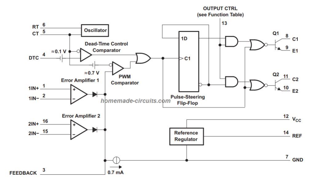
But it is a full article and not a clear photo. (see figure 1.) an internal−linear sawtooth oscillator is frequency− programmable by two external.
My friend sent me this circuit.

Layout pwm tl494. Here are a few examples: Using tl494 for the design. Tl494, ncv494 www.onsemi.com 6 applications information description the tl494 is a fixed−frequency pulse width modulation control circuit, incorporating the primary building blocks required for the control of a switching power supply.
Rangkaian inverter dc ke ac panduan teknisi sumber : For this configuration, you can get your output in parallel modes. The ic tl494 is a specialized pwm ic and is designed ideally to suit all types of circuits which require precise pwm based outputs.
The "rem" section on the dc dc power supply circuit with tl494 pwm control integration. The tl494 ic has 8 functional blocks which are shown and described below. As we mentioned earlier, the tl494 is a pwm controller circuit.
He said it is a very good high current dc motor controller. In this articles we discuss in detail regarding the main functions of the ic, and also how to use it in practical circuits. The circuit diagram is below.
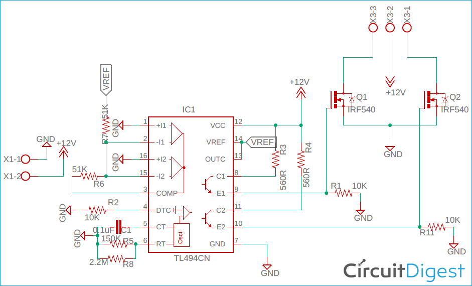
The mosfets irf1010n driven at the output of tl494 can be replaced by irf3205, irfz44, 50n06. The tl494 fixed frequency pwm controller can be used for dc to dc conversion regardless of buck or boost topology. 12v dc motor speed control pwm circuit using tl494 sumber www.eleccircuit.com.
Fig:3 th components layout of this project. By debashis das mar 04, 2020 2. I am designing a circuit with tl494.
When i run my model in orcad it gives me many of this annoying error: Pwm controller (up to 200 khz) the tl494 pwm controller incorporates all the functions required in the construction of a pulse width modulation (pwm) control circuit on a single chip. 2x100w class d amplifier circuit tl494 smps power supply schematic circuit diagram.
A cable from the ignition wire of the car will be pulled in. In this tutorial we'll discuss how pwm works and see how you can implement pwm yourself. Tl494 can be used to provide a constant current by varying the output voltage to the load.
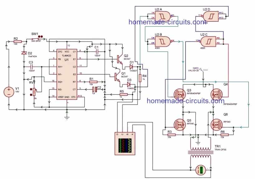
Cost isolated flyback converter with the tl494. A pwm inverter is a type of circuit that uses modified square waves to simulate the effects of alternating current (ac), which is suitable for powering most of your household appliances. Pwm inverter circuit diagram using tl494 car amplifier circuit tip142 tip147 200w dc dc tl494 ei33 300watt inverter circuit diagram pcb layout in 2020 circuit forum for electronics.
I also found the way to create a pwm controller from christophe basso's literature but now i haven't the time to work on it. So, does anyone have any idea what i can do? I've been told that this model is just for schematic purposes and i cannot use it for simulation.
Double dc motor control using pulse width modulation this project is based on the single pwm project. The nodes are all connected tothis tl494. Less than 2 connections at node.
An inverter is a circuit that converts direct current (dc) to alternating current (ac ). You can easily configure this design by building a 5v/10a switching power supply buck. Tl494, pulse width modulation(pwm) reg1:
Where to use the tl494 pwm controller ic. The schematic diagram is based on the design case presented in the reference [1], designing switching voltage regulators with the tl494, texas instruments application report. Everything has just been doubled.
The circuit board and motors are shown on the right, connected to the k8055. I tryied to work with sg1525a but that model request modification into the netlist and into the.option. Pwm inverter circuit using tl494.
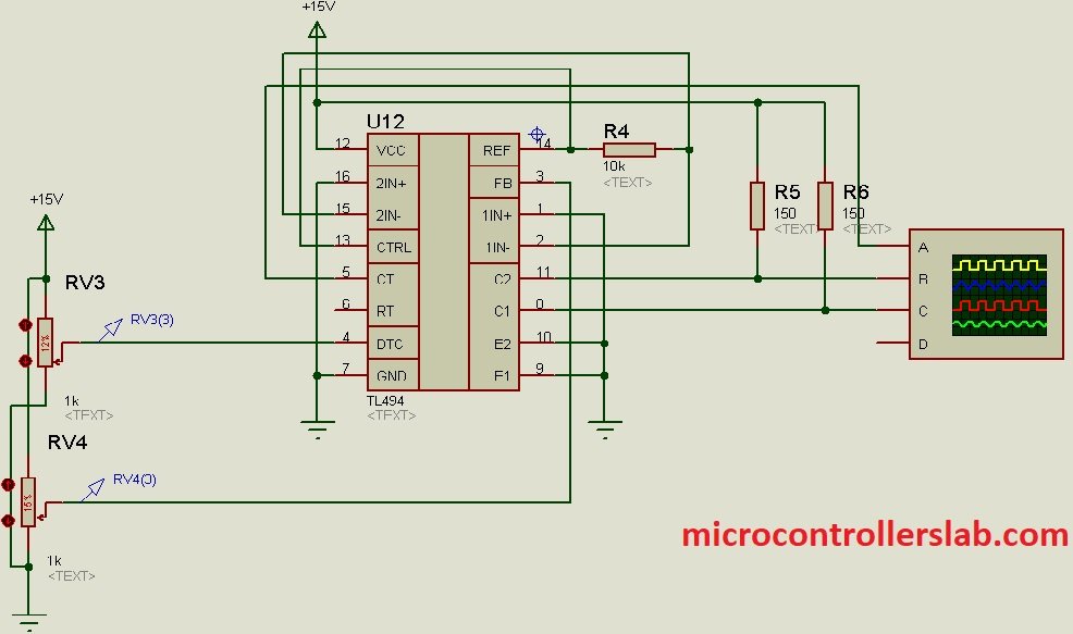
The circuit diagram and a suggested pcb layout are below. Before current mode control was successfully implemented, the tl494 pwm mode ensured low emi and noise operation due to its trailing edge modulation technique. Tl494 datasheet, pinout, application circuits.
Layout inverter tl494 layout pcb inverter ic tl494 pcb · skema smps tl494 smps tl494 final versi 1 unregulated · pwm inverter circuit diagram. The ic tl494 is a versatile pwm control ic, which can be applied in many different ways in electronic circuits. Persamaan ic tl494, skema rangkaian inverter ic tl494,.
I'm searching to simulate a voltage mode pwm power supply using tl494. Understanding pwm and implementing it yourself introduction. Component selection and magnetics design is also shown.

Soft Start Circuit For Dc Motor inspire ideas 2022
Kapanadze Cousin DALLY FREE ENERGY

Layout Pwm Tl494 Ov 9014 Tl494 Pwm Controller Circuit
skema converter dc to dc ic tl494 SHEMS

TL494 PWM IC Pinout, Examples, Features, Datasheet and
skema layout pwm tl494 smps SHEMS
skema tl494 for pwm power D SHEMS

TL494 Adjustable Switch Mode Power Supply (Universal buck

Inverter Circuit Diagram Using Tl494 Home Wiring Diagram

Tl494 Pwm Controller Circuit Design Youtube Wiring

Layout Pwm Tl494 Ov 9014 Tl494 Pwm Controller Circuit
The circuit chart. 1Oscillator PulseWidthModulation
Skema Layout Pcb Inverter PCB Circuits

TL494 Datasheet, Pinout, Application Circuits Homemade


