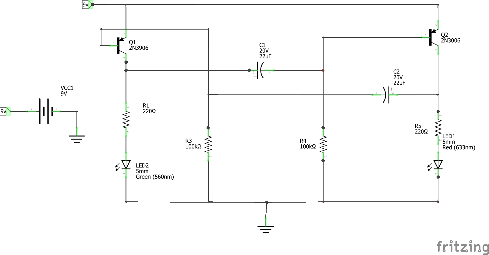
The other two variants are subscription based software and have additional features like more schematic. The first step in successfully creating a pcb is the proper creation of an appropriate schematic.

Autodesk Eagle Pcb Layout Basics Part 3 PCB Circuits
Contamination of the pcb surface by flux residues, deposited salts, and other debris can create leakage paths between circuit nodes.

Pcb layout basics part 3. In static printed circuit board designs, leakage resistance is the dominant effect. This tutorial will breakdown what makes up a pcb and some of the common terms used in the pcb world. In this part, we discuss schematic drawing and footprint selection as well as transferring the design to layout.
This article outlines an example design flow. For some designers, the pcb design will be a natural and easy extension of the design process. But the rounded corners may be difficult to machine.
Whether you are moving at a high speed or you're designing a high speed printed circuit board, good design practices help ensure your design will work as intended and can be manufactured at volume. What are the advantages and disadvantages, and how to choose? More on this will be covered in another article.
When pcb is not developed, at that time all components are connected with a wire which increases complexity and decreases reliability of. In this final section on pcb layout, we're going to look at reduced schematics from the. Copper pour basics (3 videos) copper pour (also known as copper polygons), a very useful and widely used basic functionality of every good pcb design software.
In the picture above, there are traces that electrically connect the various connectors and components to each other. The schematics is usually created with the same software to be used for pcb design. This involves creating the layout.
Creating components (part 3) this video describes how to create a component model. In this guide, we've compiled some of the essential pcb layout guidelines that apply to most modern circuit boards. Videos you watch may be added to the tv's watch history and influence tv recommendations.
If you have been following along on our journey so far, then you know that we are closing in on the end of the road for your schematic journey. A pcb allows signals and power to be routed between physical devices. The thick red lines represent traces on the toplayer.
With all the components to be used identified, the circuit is then designed with tests and simulations going on simultaneously to ensure it performs as desired. In this part, we discuss schematic drawing and footprint selection as well as transferring the design to layout. You can use it to create a solid area on a pcb layer to lower your power tracks impedance, increase maximum current, use it as a heat sink or rf shield.
Pcb is an acronym for printed circuit board. Greetings and welcome back to schematic basics part 3! I have selected kicad software to explain pcb tutorials.
The articles are written in the context of the national instruments circuit design tools ni multisim and ni ultiboard. How to design pcb using eagle (printed circuit. Pcb design tutorial by david l.
Open your pcb layout (.brd) file from your autodesk eagle control panel. Part one of this article, pcb design basics, outlines the major terminology in pcb design. You're in complete control of the autorouter setup with settings.
From the perspective of impedance matching, these two lines can be made into matching bends. Part one of this article, pcb design basics, outlines the major terminology in pcb design. It is a board that has lines and pads that connect various points together.
It has gnu and gpl licenses. One of the key concepts in electronics is the printed circuit board or pcb. Since it is open source software, anyone can try this and practice my tutorials.
December 7, 2010 embedded staff. For example, with a thickness of 0.25mm, a trace width of 0.35mm gives 50ω, far easier to use. Pcb layout basics 3 | eagle | blog 01.10.2017 · eagle free, as the name suggests, is a free to use pcb design software which can be used for capturing schematics and pcb layout.
Jones page 3 of 25 3 introduction you've designed your circuit, perhaps even bread boarded a working prototype, and now it's time to turn it into a nice printed circuit board (pcb) design. It's so fundamental that people often forget to explain what a pcb is. If playback doesn't begin shortly, try restarting your device.
Pcb layout basics for engineers. To do thi we look at using schematic symbols and pcb footprints.

KiCad 3.0 PCB Layout with PCBnew Getting To Blinky

Autodesk Eagle Schematic Basics Part 3 Circuit Boards

Review of Server PCB Layout & Schematic Part 3

Getting Started with EasyEDA Part 3 PCB Layout EasyEDA

Getting Started with EasyEDA Part 3 PCB Layout EasyEDA

How to Build Your Own Flight Controller // Basic PCB

Autodesk Eagle Pcb Layout Basics Part 3 PCB Circuits

Getting Started with EasyEDA Part 3 PCB Layout EasyEDA

Getting Started with EasyEDA Part 3 PCB Layout EasyEDA

PCB Layout for EMC Power Supply Design Tutorial Section

Getting Started with EasyEDA Part 3 PCB Layout EasyEDA

Getting Started with EasyEDA Part 3 PCB Layout EasyEDA
Autodesk Eagle Schematic Basics Part 3 Circuit Boards

Bipolar Transistor Cookbook — Part 3 Nuts & Volts

Getting Started with EasyEDA Part 3 PCB Layout Shawn Hymel

PCB Tutorial Schematics (Part 3) YouTube
Getting Started with EasyEDA Part 3 PCB Layout Shawn Hymel
